CYX31 series pressure sensor
2020年5月17日
This is a product example, mainly for effect display
2020年6月23日


CYX50 series pressure sensor
CYX50 series oil injection core pressure sensors use internationally advanced high-stability, high-precision silicon pressure chips, adopt stress-optimized design sintering seat, through patch, gold wire bonding, diaphragm pure plane welding, high vacuum oil injection, pressure cycle to Production by stress, high temperature aging, temperature compensation and other processes. The assembly size and sealing method of CYX50 series conform to the international 50 chuck…
1 Summary
CYX50 series oil injection core pressure sensors are produced with international advanced high stability and high precision silicon pressure chip, sintered seat with stress optimized design, through patching, gold wire bonding, diaphragm pure plane welding, high vacuum oiling, pressure cycle stress relief, high temperature aging, temperature compensation and other processes.
CYX50 series assembly size and sealing method conform to the international 50 clamp interface standard, with good interchangeability. It is mainly used in pharmaceutical, food and other industries with high clean requirements for pressure testing.
2 Product features
- Measuring range -100kPa~0kPa~10kPa…6MPa
- Pressure type: gauge pressure (G), absolute pressure (A) and seal gauge pressure (S)
- Constant current / voltage power supply
- Isolated structure, suitable for multiple fluid media
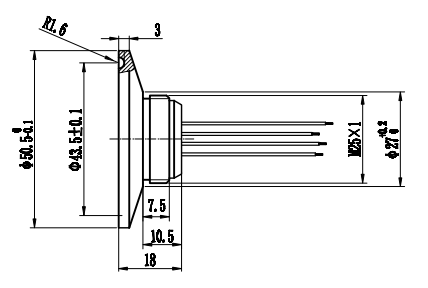
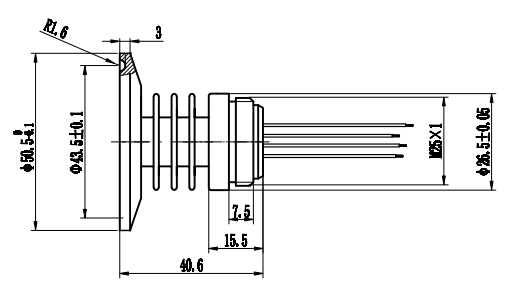
- Φ 50.5mm standard pressure sensor
- All 316L stainless steel
3 Applications
- Medicine
- Food
- Industrial process control
- Liquid level measurement of pressure vessel
4 Technical indicators
4.1 Electrical performance
- Power supply: ≤ 0mA; DC ≤ 10V DC
- Electrical connection: 0.2mm24-color 100 mm silicone rubber flexible conductor
- Common mode voltage output: 50% of current mode input (typical value), 40% of voltage type input (typical value)
- Input impedance: 2.7K Ω ~ 5K Ω
- Output impedance: 3.0k Ω ~ 6K Ω
- Response time (10% ~90%): < 1ms
- Insulation resistance: 500M Ω / 100V DC
- Allowable overvoltage: 1.5 times of full scale
4.2 Structural performance
- Diaphragm material: stainless steel 316L
- Shell material: stainless steel 316L
- Pressure lead-in tube material: stainless steel 316L
- Pin lead: gilded Kovar
- Sealing ring: silicone rubber
- Net weight: about 160g
4.3 Environment condition
- Vibration: no change at 10gRMS, (20-2000) Hz
- Constant acceleration: 100g, 11ms
- Media compatibility: liquid or gas compatible with 316L and silicone rubber
4.4 Reference conditions
- Medium temperature: (25 ± 3) ℃
- Ambient temperature: (25 ± 3) ℃
- Humidity: (50% ± 10%) RH
- Ambient pressure: (86-106) kPa
- Power supply: (1.5 ± 0.0015) mA DC
4.5 Standard range sensitivity output and optional pressure form
|
Range |
full rangeOutput (mV) |
Pressure form |
|
Range |
full rangeOutput (mV) |
Pressure form |
|
0~10kPa |
(30~120) ±20 |
G |
0~400kPa |
(40~150) ±20 |
G/A |
|
|
0~35kPa |
(40~120) ±20 |
G/A |
0~1.0MPa |
(55~145) ±20 |
G/A |
|
|
0~70kPa |
(20~140) ±20 |
G/A |
0~2.0MPa |
(50~160) ±20 |
G/A |
|
|
0~100kPa |
(50~145) ±20 |
G/A |
0~3.5MPa |
(60~150) ±20 |
G/S/A |
|
|
0~200kPa |
(30~125) ±20 |
G/A |
0~6.0MPa |
(60-130) ±20 |
S |
4.6 Basic parameters
|
Parameters |
Typical value |
Maximum |
Single |
|
Full scale output |
100 |
250 |
mV |
|
Zero output |
±1 |
±2 |
mV |
|
Nonlinearity |
0.2 |
0.5 |
%FS |
|
Hysteresis |
0.05 |
0.08 |
%FS |
|
Repeatability |
0.05 |
0.08 |
%FS |
|
Input/output impedance |
2.6 |
5.0 |
kΩ |
|
Zero temperature drift (note 1) |
±0.4 |
±1.0 |
%FS,@25℃ |
|
Sensitivity temperature drift (note 2) |
±0.4 |
±1.0 |
%FS, @25℃ |
|
Long-term stability |
0.2 |
0.3 |
%FS/year |
|
Excitation current |
1.5 (Maximum input voltage 10V) |
mA |
|
|
Insulation resistance |
500(100VDC) |
MΩ |
|
|
Compensation temperature (note 3) |
0~50;-10℃~70℃ |
℃ |
|
|
Working temperature |
-40~+125/+150 |
℃ |
|
|
storage temperature |
-40~+125 |
℃ |
|
|
Response time |
≤1 |
ms |
|
|
Housing and diaphragm materials |
Stainless steel 316L |
|
|
|
O-ring |
Silicone Rubber |
|
|
|
Measuring medium |
Fluid compatible with 316L, silicone rubber |
|
|
|
Life (25℃) |
> 1 × 10⁸ pressure cycle (80% FS) |
Times |
|
|
Filling medium |
Silicone oil |
|
|
|
Sealing ring |
Various specifications, user-defined |
|
|
|
Note 1 & 2. 0-10kPa zero temperature drift and sensitivity temperature drift: typical value is 0.5% FS @ 25 ℃, maximum value is 1.2% FS @ 25 ℃. Note 3. compensation temperature 0~ +50 ℃ for ranges ≤ 200kPa; – 10℃~ +70 ℃ for ranges >200kPa. |
|||
5 Model structure selection
5.1 Model selection
|
Series |
Range |
Model |
Outline drawing |
|
CYX50 |
-100kPa~7MPa |
CYX5001 (-40℃~+125℃) |
|
|
CYX5002 系列 (-40°C~150°C) |
|
||
|
CYX5003 (-40℃~+150℃)
|
|

5.2 Selection Guide

6 Schematic diagram and wiring mode

|
IN + (red wire) – power supply positive |
|
IN – (black wire) – power supply negative |
|
S + (yellow wire) – output positive |
|
S – (blue wire) – output negative |
7 Application tips
- Taking care to protect the front diaphragm of the pressure sensor and the compensation circuit board at the rear end so that the performance of the pressure sensor will not be affected or the pressure sensor will be damaged by bruising.
- Do not press the metal diaphragm with hands or hard objects to avoid damage to the pressure sensor due to chip deformation or perforation.
- Keep the rear vent pipe of the G-type pressure sensor connected to the atmosphere; prohibit water, water vapor or corrosive media from entering the reference chamber at the rear of the pressure sensor.
- Avoid dropping and bumping, etc., which will affect the stability of the product.
- If there is any change in the pin lead, the label carried by the pressure sensor shall prevail.


