
CYBK0400 Series Digital Display Pressure Switch
2022年4月8日


CYX19-007GfG PressureSensor
1 Summary
CYX19-007GfG is our newly launched oil injection core pressure sensor with the minimum pressure range. The appearance, assembly dimension and sealing mode of the product are consistent with CYX19 series. It can be applied to the detection of pressure, liquid level and flow within 10kPa.
2 Product features
- measurement range: 0kPa ~ 7kPa
- pressure form: gauge pressure (G)
- constant current / voltage supply
- isolated structure, suitable for multiple fluid media
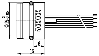
- Φ 19mm standard OEM pressure oil injection core
- all 316L stainless steel
3 Application
- industrial process control ● liquid level measurement
- gas and liquid pressure measurement ● medical system
- heating ventilatingand air conditioning
4 Technical indicators
4.1 Electrical performance
- power supply: ≤ 3.0mA; DC ≤ 10V DC
- electrical connection: four colors2mm² ×100mm silicon rubber flexible wires
- common-mode voltage output: 50% of current type input (typical value), 40% of voltage type input (typical value)
- input impedance: 2.6kΩ ~ 6kΩ
- output impedance: 4kΩ ~ 6kΩ
- response time (10% – 90%): < 1ms
- insulation resistance: 500MΩ / 100V DC
- allowable overvoltage: 3times of full scale
4.2 Structure performance
- diaphragm material: stainless steel 316L
- shell material: stainless steel 316L
- pin lead: gilded Kovar
- sealing ring: NBR, Viton (optional)
- net weight: about 23g
4.3 Environment condition
- vibration: no change under10gRMS, (20-2000) Hz
- constant acceleration: 100g, 11ms
- media compatibility: liquid or gas compatible with 316L and NBR (Viton optional)
4.4 Reference conditions
- medium temperature: (25 ± 3) ℃
- ambient temperature: (25 ± 3) ℃
- humidity: (50% ± 10%) RH
- ambient pressure: (86-106) kPa
- power supply: (1.5 ± 0.0015) mA DC
4.5 Basic parameters
|
Parameters |
Typical value |
Max value |
Unit |
|
Full scale output |
65 |
80 |
mV |
|
Zero output |
±1 |
±2 |
mV |
|
Nonlinearity |
0.2 |
0.5 |
%FS |
|
Hysteresis |
0.05 |
0.08 |
%FS |
|
Repeatability |
0.05 |
0.08 |
%FS |
|
Input / output impedance |
2.6 |
6.0 |
kΩ |
|
Zero temperature drift |
±0.5 |
±1.0 |
%FS,@25℃ |
|
Sensitivity temperature drift |
±0.5 |
±1.0 |
%FS, @25℃ |
|
Long-term stability |
0.1 |
0.2 |
%FS / year |
|
Excitation current |
1.5 (the maximum input voltage can be 10V) |
mA |
|
|
Insulation resistance |
500(100VDC) |
MΩ |
|
|
Compensation temperature |
0~50 |
℃ |
|
|
Working temperature |
-40~+125 |
℃ |
|
|
Storage temperature |
-40~+125 |
℃ |
|
|
Response time |
≤1 |
ms |
|
|
Housing and diaphragm material |
stainless steel 316L |
|
|
|
O-ring |
viton, nitrile rubber, silicone rubber |
|
|
|
Measuring medium |
Fluids compatible with 316L, NBR or Viton or silicone |
|
|
|
Life (25 ℃) |
> 1 × 10⁸ pressure cycle (80% FS) |
times |
|
|
Filling medium |
silicone oil |
|
|
|
Sealing ring |
Φ 16 × 1.8mm (nitrile or fluorinated rubber (note 1)) |
|
|
5 Model structure selection
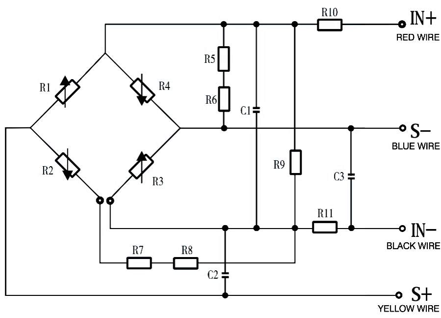
6 Schematic diagram and wiring mode
|
IN + (red wire) – power supply positive |
|
IN – (black wire) – power supply negative |
|
S + (yellow wire) – output positive |
|
S – (blue wire) – output negative |
|
C1~C3 capacitors are 103 porcelain dielectric capacitors, and battery power supply can be omitted according to user requirements. |
||
7 Application Tips
- In the compensation circuit, the positive power supply to ground and the positive and negative output to ground are respectively increased by 0.01μ F ceramic dielectric capacitor to improve the anti-interference ability of thesensor. Customers who need intermittent power supply and rapid response can require no capacitor in the purchase
- The “floating” sealing structure of O-ring on the side wall is recommended for sealing the pressure core, which can avoid the front end being compressed and the stability being affected.
- Pay attention to protect the front diaphragm and the compensation circuit board at the rear end, so as not to affect the performance or cause damage to the pressure sensor.
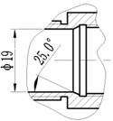
- The shell cavity shall be designed with tapered angle as shown in the figure, which is easy for assembly and can prevent the seal ring from being scratched by right angle.
- During assembly, pay attention to the tolerance fit between the pressure sensor size and the inner shell of the transmitter. It is recommended that the cavity be processed according to + 0.02 – + 0.05 of the pressure sensor diameter to achieve the required air tightness.
- During assembly, it is required to place vertically and press down evenly to prevent the shell from jamming or damaging the compensation plate.
- Do not press the metal diaphragm with hands or hard objects to avoid damaging the pressure sensor due to chip deformation or perforation.
- When wiring, the pins should not be cut too short, the length is generally no less than 5mm, and the welding time is no more than 5s.
- The pressure lead-in tube at the back of G type pressure sensor shall be connected with the atmosphere; water, steam or corrosive medium shall not enter the reference cavity at the back of the sensor body.
- Avoid falling, crashing, etc., which will affect the stability of the product.
- In case of any change of pin lead, the label with the pressure sensor shall prevail.


