
CYX23/25 series pressure sensor
2020年5月17日CYX50 series pressure sensor
2020年5月17日

CYX31 series pressure sensor
CYX31 series oil injection core pressure sensor is a joint type high temperature flat membrane pressure sensor. The core body of the high-temperature joint increases the heat sink through the pressure chip. The welding diaphragm at the front of the thread is filled with silicone oil to conduct the pressure. The joint part can withstand a high temperature of up to 200 ℃ to meet the needs of high temperature pressure measurement
1 Summary
CYX31 series oil injection core pressure sensor is a connector type high temperature flat membrane pressure sensitive device. The high-temperature connector pressure sensor can withstand high temperatures up to 200°C by moving the pressure chip back and adding a heat sink and the welded diaphragm at the front of the thread is filled with silicone oil to conduct pressure, meeting the needs of high-temperature pressure measurement.
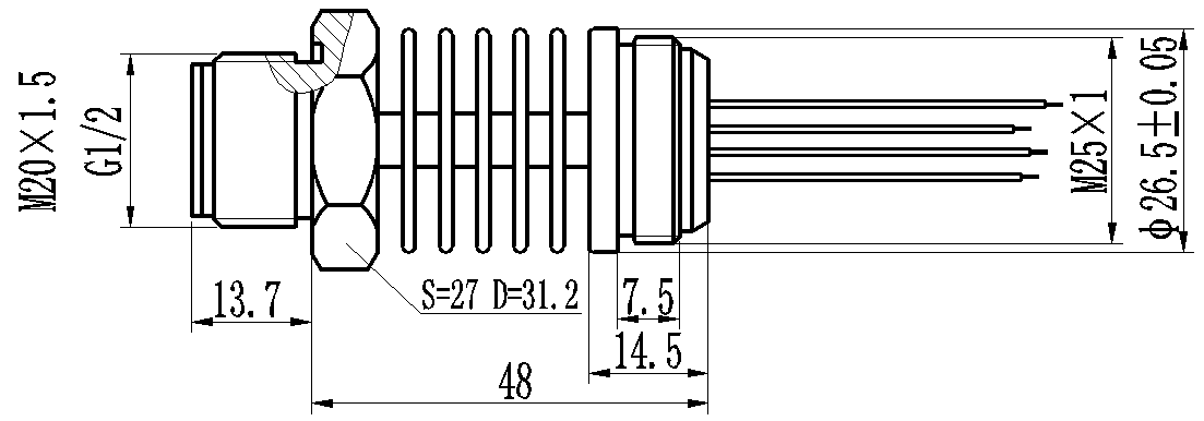
1.1 CYX31 series pressure sensor recommended threads
The recommended standard thread connector is M20×1.5, G1/2, other threads need to be customized. The products are used for pressure detection of media compatible with 316L stainless steel and NBR or Viton.
1.2 Negative pressure measurement, gauge type CYX31 series pressure sensor model followed by Y
The negative pressure type pressure sensor is produced by a special process for negative pressure, which can reliably complete the detection of lower than atmospheric pressure, with a range between -100kPa to 3MPa arbitrarily selected.
2 Product features
- Measuring range: 0kPa ~ 35kPa…10MPa
- Pressure type: gauge pressure (G),absolute pressure (A) and seal gauge pressure (S)
- Constant current / voltage power supply
- Isolated structure, suitable for multiple fluid media
- Process thread: M20×1.5 or G1/2
- All 316L stainless steel
3 Applications
- Industrial process control
- Liquid level measurement
- Gas and liquid pressure measurement
- Pressure switches and hydraulic systems
- Medical and food equipment
4 Technical indicators
4.1 Electrical performance
- Power supply: ≤0mA; DC ≤ 10V DC
- Electrical connection: 0.2mm24-color 100 mm silicone rubber flexible conductor
- Common mode voltage output: 50% of current mode input (typical value), 40% of voltage type input (typical value)
- Input impedance: 2.7KΩ ~ 5K Ω
- Output impedance: 3.0k Ω~ 6K Ω
- Response time (10% ~90%): < 1ms
- Insulation resistance: 500M Ω/ 100V DC
- Allowable overvoltage: 1.5 times of full scale
4.2 Structural performance
- Diaphragm material: stainless steel 316L
- Shell material: stainless steel 316L
- Pressure lead-in tube material: stainless steel 316L
- Pin lead: gilded Kovar
- Sealing ring: NBR, Viton (optional)
- Net weight: about 150g
4.3 Environment condition
- vibration: no change at 10gRMS, (20-2000) Hz
- constant acceleration: 100g, 11ms
- media compatibility: liquid or gas compatible with 316L and NBR (Viton optional)
4.4 Reference conditions
- medium temperature: (25 ± 3) ℃
- ambient temperature: (25 ± 3)℃
- humidity: (50% ± 10%) RH
- ambient pressure: (86-106) kPa
- power supply: (1.5 ± 0.0015) mA DC
4.5 Standard range sensitivity output and optional pressure form
|
Range |
full range |
pressure |
|
Range |
full range |
pressure |
|
0~35kPa |
(40~120) ±20 |
G/A |
0~1.0MPa |
(55~145) ±20 |
G/A |
|
|
0~70kPa |
(20-140) ±20 |
G/A |
0~2.0MPa |
(50~160) ±20 |
G/A |
|
|
0~100kPa |
(50~145) ±20 |
G/A |
0~3.5MPa |
(60-150) ±20 |
G/S/A |
|
|
0~200kPa |
(30-125) ±20 |
G/A |
0~6.0MPa |
(60~130) ±20 |
S |
|
|
0~400kPa |
(40~150) ±20 |
G/A |
0~10MPa |
(40~110) ±20 |
S |
4.6 Basic parameters
|
Parameters |
Typical value |
Maximum |
Single |
|
Zero output |
±1 |
±2 |
mV |
|
Non-linear |
0.2 |
0.5 |
%FS |
|
Late |
0.05 |
0.08 |
%FS |
|
Repeatability |
0.05 |
0.08 |
%FS |
|
Input/output impedance |
2.6 |
5.0 |
kΩ |
|
Zero temperature drift 1 |
±0.4 |
±1.0 |
%FS,@25℃ |
|
Sensitivity temperature drift 2 |
±0.4 |
±1.0 |
%FS, @25℃ |
|
Long-term stability |
0.2 |
0.3 |
%FS/年 |
|
Excitation current |
1.5(Maximum input voltage 10V) |
mA |
|
|
Insulation resistance |
500(100VDC) |
MΩ |
|
|
Compensation temperature |
0~50;-10℃~80℃ |
℃ |
|
|
Operating temperature |
-40~+150(Threaded part) |
℃ |
|
|
storage temperature |
-40~+125 |
℃ |
|
|
Response time |
≤1 |
ms |
|
|
Housing and diaphragm materials |
316L stainless steel |
|
|
|
ED sealing ring |
Fluorine rubber, nitrile rubber |
|
|
|
Measuring medium |
Fluid compatible with 316L, nitrile rubber or fluoroelastomer |
|
|
|
Life (25℃) |
>1×10⁸ pressure cycle (80%FS) |
次 |
|
|
Filling medium |
Silicone oil |
|
|
|
ED sealing ring |
Φ23.9×Φ18.5×1.5mm (Dingqing or fluorinated rubber Note 3) |
|
|
|
Note 1, Note 2: The typical value of zero to 10 kPa temperature drift and sensitivity temperature drift is 0.5%FS@25℃, and the maximum value is 1.2%FS@25℃. Note 3: The temperature resistance range of fluororubber seals is -20℃~200℃, the low temperature performance is poor, when the temperature range is lower than -20℃, please verify the sealing. |
|||
5 Type selection structure
6 Schematic diagram and wiring
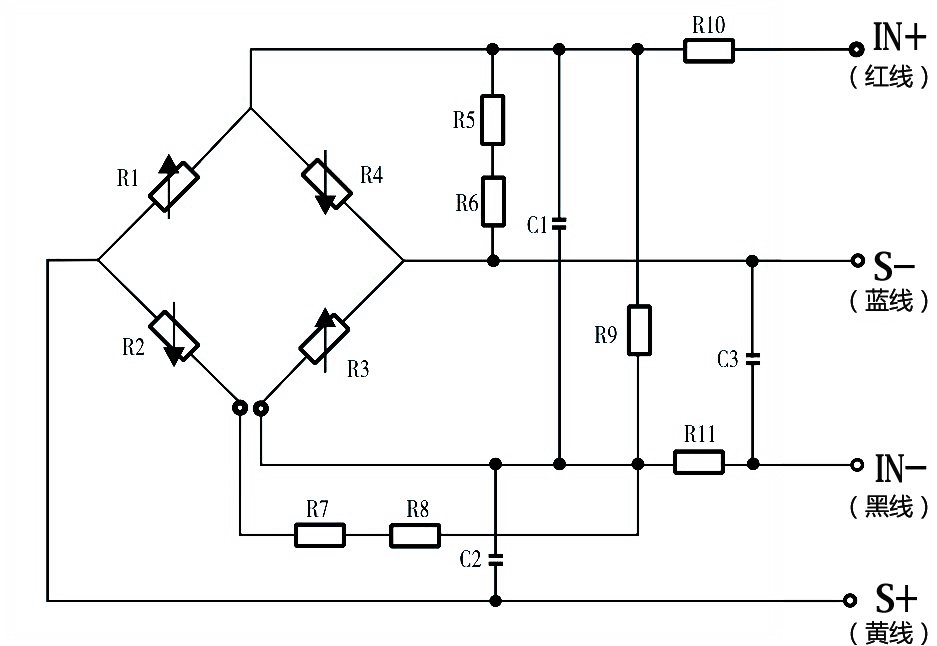
IN+(red line)-power supply positive IN-(black line)-power supply negative S+(yellow line)-output positive S-(blue line)-output negative
7 Application tips
● The hexagonal ED seal ring structure is recommended for the sealing method of the pressure core. When installing the thread, avoid excessive torque affecting the stability of the pressure core. It is recommended that the torque pressure range is not greater than the following values: 0 ~ 500kPa, 0.9Nm; 500kPa ~ 2MPa, 1.1Nm; 2MPa ~ 10MPa, 1.6Nm.
● Pay attention to protect the front diaphragm of the pressure core and the compensation circuit board at the rear end, so as not to damage the performance of the pressure core or damage the core.
● Do not press the metal diaphragm with your hands or hard objects to avoid damage to the core due to chip deformation or perforation.
● The vent pipe at the rear of the G-type core body should be kept open to the atmosphere; it is forbidden for water, water vapor or corrosive media to enter the reference cavity at the rear of the core body.
● Avoid dropping, bumping, etc., which will affect the stability of the product.
● If there is a change in the pin lead, the actual physical label of the core shall prevail.
8 Selection guide
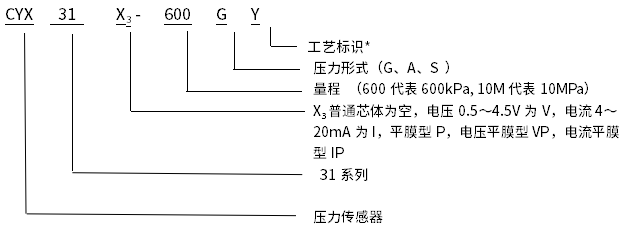
*Technology identification: f means general technology, Y means negative pressure technology.


